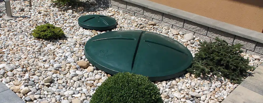
AT PLUS wastewater treatment plant - AT 6 PLUS - AT 20 PLUS
Wastewater treatment plants AT 6 PLUS - AT 20 PLUS, were invented to purify sewage water for detached houses.
AT PLUS residential wastewater treatment plants offer:
- Maximum comfort of residential wastewater treatment plant
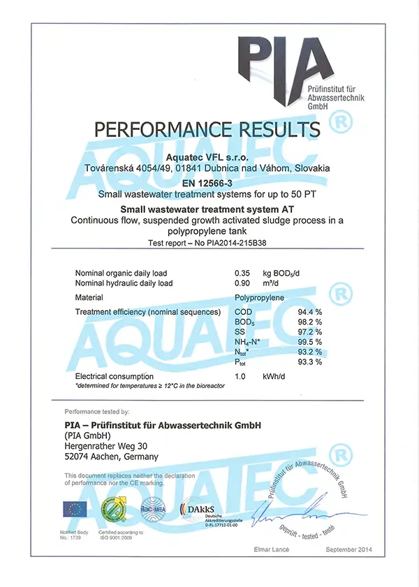
- Highest cleaning efficiency tested at the German PIA Aachen Laboratory
- Possibility of recycling the water
- Minimum requirements for WWTP operators
- Electronic management of the wastewater treatment process
- Minimum electricity consumption of WWTP
- No mechanical valves in WWTP
- Optional online monitoring and GSM reports of the state of the wastewater treatment plant
- Optional regular contractual service of WWTPs (clients in Slovakia)
- 24/7 emergency service of WWTP (clients in Slovakia)
Why is this wastewater treatment plant named AT PLUS?
Because it represents the ultimate in comfort!
Because it achieves the highest cleaning efficiency!
Because it achieves the lowest electricity consumption!
The purified wastewater can be discharged into surface or underground water, recycle it for irrigation or use it for technical purposes after filtration.
 |
TRANSPORT
within Slovakia
|
 |
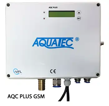
Control unit AQC PLUS GSM |
 |
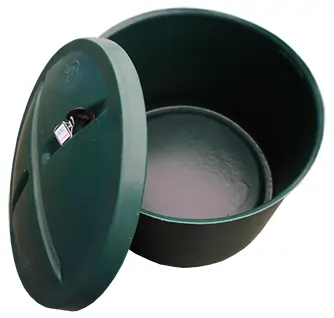
TANK FOR THE BLOWER for wastewater treatment plant |
 |
PLACING INTO PREPARED HOLE - no construction works |
 |
START of the wastewater treatment plant |
 |
Optional: REGULAR CONTRACTUAL SERVICE of the wastewater treatment plant |
 |
Design of accurate
WWTP solution
|
 |
Consulting for residential
wastewater treatment solutions
|
 |
Fast delivery times
of WWTP |
Simple installation of AT PLUS wastewater treatment plants
WWTPs of the type AT 6 PLUS to AT 20 PLUS are installed into a pit with a 15 cm thick reinforced concrete slab on the bottom, so that the upper edge of the WWTP tank overlaps about 5 cm above the terrain. If necessary, and if the design documentation requires it, the WWTP is to be concreted to the height specified by the project documentation. WWTP must be filled with the water (to the outflow pipe level) before doing the backfill. Detailed instructions for installing of WWTPs are given in the operating instructions annexed. The Aquatec VFL technical team can take care of the installation.
Aquatec VFL service and maintenance of wastewater treatment plants
For the long lifetime of each process equipment, it is necessary to provide professional service. We therefore provide wastewater treatment plants maintenance and service throughout Slovakia:
Warranty service of wastewater treatment plants
Post-warranty service of wastewater treatment plants
Regular prepaid service of wastewater treatment plants
Emergency service of wastewater treatment plants
Advantages of Aquatec VFL AT PLUS wastewater treatment plants
 |
Integrated retention chamber
for wastewater
|
|
Thickness of the WWTP
tank wall is 8 mm
|
|
10 years watertightness guarantee |
|
|
First class materials used
for wastewater treatment plants
|
|
Stainless steel locking system for
every wastewater treatment plant
|
|
100% money back guarantee |
|
|
Tested at PIA Testing Institute for Waste Water Technology
in Aachen, Germany
|
|
Remote GSM control of wastewater treatment plant |
|
24/7 service of wastewater treatment plants |
AT PLUS wastewater treatment plant package includes
 |
 |
 |
||
|
Control units for wastewater treatment plants AQC PLUS GSM |
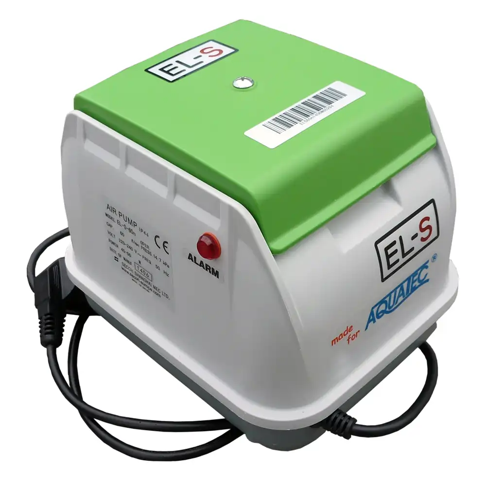
Blower for wastewater treatment plants |
Tank for the blower for wastewater treatment plants |
Technical parameters:
|
WWTP Type |
Connected persons [no.] |
Tank
diameter x height
[mm] |
Manhole diameter [mm] |
Height and DN of inflow/outflow [mm] |
Weight [kg] |
Usable volume [m3] |
Daily inflow [m3/day] |
Blower [Liter] |
Voltage [V] |
| AT PLUS 6 | 2-5 | 1400x1800 | 1400* | 1300/1150 -DN125 | 105 | 1,70 | 0,60 | 60 | 230 |
| AT PLUS 8 | 6-7 | 1400x2200 | 1400* | 1700/1500 -DN125 | 125 | 2,20 | 0,90 | 60 | 230 |
| AT PLUS 10 | 8-9 | 1750x2200 | 1400 | 1500/1250 -DN125 | 195 | 3,10 | 1,20 | 60 | 230 |
| AT PLUS 12 | 9-10 | 1750x2400 | 1400 | 1700/1500 -DN125 | 225 | 3,70 | 1,50 | 80 | 230 |
| AT PLUS 15 | 11-15 | 2050x2200 | 1400 | 1700/1500 -DN150 | 330 | 5,10 | 1,95 | 100 | 230 |
| AT PLUS 20 | 16-20 | 2050x2700 | 1400 | 2200/2000 -DN150 | 440 | 6,70 | 2,70 | 120 | 230 |
* according to selected solution 600 mm
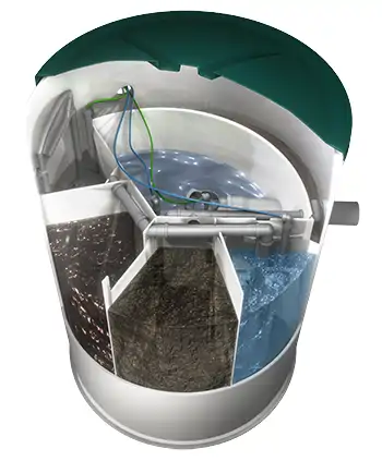
The technological process in the AT PLUS wastewater treatment plant
It consists of a sequence of several technological processes. Wastewater flows into a non-aerated space, where nitrogen is biologically degraded and conditions are created for partial phosphorus biologically degraded.
In this part, mechanical pre-treatment of the incoming wastewater and decomposition of solid pollution also occurs. The non-aerated activation space is divided by several internal dividing walls forming a vertically flowing labyrinth, in which internal circulation is established.
Next, the wastewater flows by gravity into an aerated space with low-load activation, where, in the presence of oxygen, biological degradation of organic pollution and nitrification of ammonia nitrogen occur. Air is supplied to the aeration system by membrane compressors or side channel blowers (high-pressure fans), which are located outside the biological reactor. Compressed air is blown into the aerated space through fine-bubble aeration elements. The compressed air supplied by membrane compressors is controllable by a control unit (microprocessor control unit) and divided by a solenoid valve into different sections in the WWTP (without manual air distributor), with which the treatment plant can operate in different modes depending on the load. The WWTP or the control unit can be controlled manually, automatically based on the water inflow to the WWTP or remotely via a GSM connection.
The next stage of treatment is separation, where the purified water is separated from the activated sludge, while the purified water is discharged into the water flow, into the infiltration or recycled and the separated activated sludge is returned to the system by pumping from the bottom of the settling space to the non-aerated or aerated space. The settling chamber contains a flow restrictor, which allows the built-in retention space in the treatment plant to be used in the event of sudden inflows of wastewater and prevents the treatment plant from being overloaded. This creates conditions for the discharge of wastewater by infiltration into groundwater and for the recycling of biologically treated wastewater, as the discharged water does not clog the pores of the subsoil filter layer or the filter device.
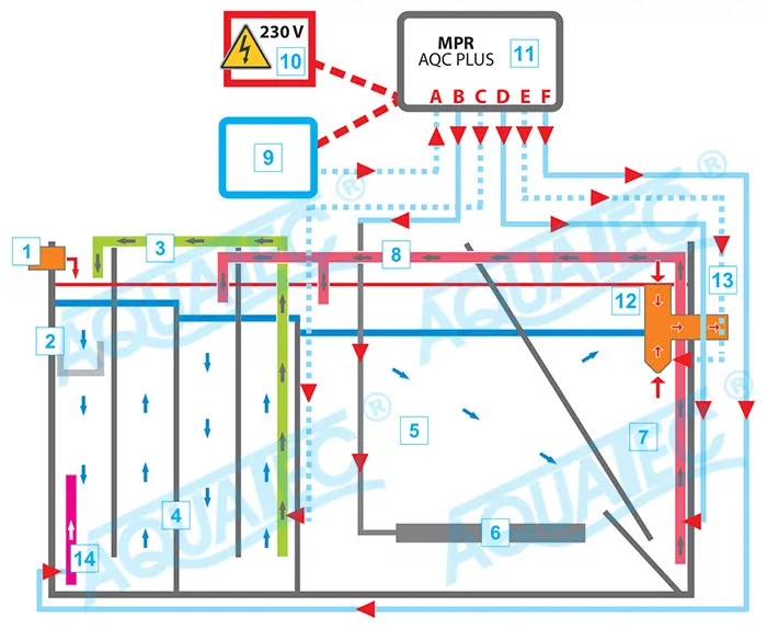
1 - Inlet
2 - Basket for collecting coarse dirt
3 - Recirculation of non-aerated space - airlift
4 - Anaerobic and anoxic chambers
5 - Oxic chamber
6 - Fine-bubble diffusor
7 - Final clarification chamber
8 - Recirculation of return sludge - airlift
9 - Blower
10 - Power supply 230 V, 50 Hz
11 - Microprocessor control unit AQC Plus (GSM)
12 - Flow regulator
13 - Outlet
14 - Mixing of mechanical pre-treatment with coarse bubble - airlift
European Union
The AT wastewater treatment plant with a built-in retention space already meets the requirements of the EU standard for resistance to sudden inflowing wastewater and ensures uniform operation of the domestic wastewater treatment plant even with sudden discharge of a larger volume of water (e.g. bathtub + washing machine). This solves the main problem of domestic wastewater treatment plants with the flushing of activated sludge from the wastewater treatment plant with each surge inflow.